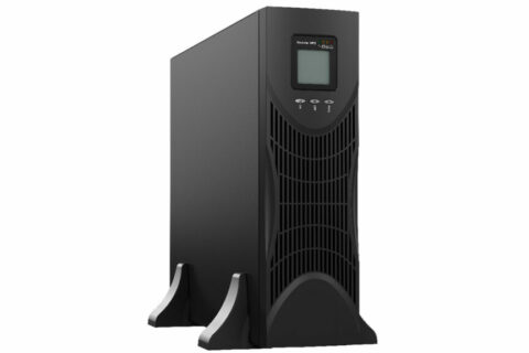
MSS – EMERGENCY POWER SUPPLIES EN50171 SINE WAVE 0.75-7.5KW SINGLE PHASE
Emergency Centralized Power Supply to EN 50171
- 120% CONTINUOUS OVERLOAD
- BATTERY REVERSAL PROTECTION
- HIGH CHARGING CURRENT
- CASING WITH HIGH MECHANICAL PROTECTION
- BATTERY LIFE EXPECTANCY 10 YEARS
- RESTORE TO 80% AUTONOMY WITHIN 12 HOURS AFTER DEEP DISCHARGE
OPERATING MODE
The CEI EN 50171 standard provides for different types of operation; In practical cases, 2 main operating modes are used, described below.
NON-STOP OPERATION (Always on)
In this mode, the load is permanently supplied by the SCO system via the inverter (fig.3). When the input grid fails, it is always the inverter, through the energy supplied by the batteries, to power the load (fig.4). When switching from the mains condition to the mains condition no input, there is no interruption to the power supply to the load, hence the name “uninterrupted” mode.
In this mode, the static bypass of the SCO system works only in the event of a failure of the SCO itself, or is used, together with any manual bypass, for system maintenance purposes
NON-PERMANENT SWITCHING OPERATION (Emergency only)
This mode is used in cases where the security systems require power only when the mains fails, for example emergency lighting systems that only work in emergencies (the so-called S.E. Emergency Only systems).
In mains conditions the load is not supplied with power (fig5). In the event of a mains failure, the SCO device supplies power to the safety devices connected to it, also in this case within a time of 0.5 seconds from the mains failure (fig.6)
OPERATION WITH PERMANENT (always on)/NON-PERMANENT (emergency only) switching
This mode represents the combination of modes 1 and 3 so that one load can be permanently powered (even in the absence of the mains) and at the same time power to another only in the absence of the mains. When the network is present, the “emergency only” load is not powered
| MODEL | MSS01 | MSS02 | MSS03 | MSS06 | MSS10 | |||
| POWER RATING | 1KVA | 2KVA | 3KVA | 6KVA | 10KVA | |||
| Active power | 0.9kW | 1.8kW | 2.7kW | 5.4kW | 9kW | |||
| Active power according to EN50171 | 0.75kW | 1.5kW | 2.25kW | 4.5kW | 7.5kW | |||
| INPUT | Input | Single phase | ||||||
| Power factor | THDV input ≤1% | |||||||
| Voltage rating | 220VAC / 230VAC / 240VAC | |||||||
| Rated Frequency | 50Hz/60Hz Auto Selection | |||||||
| Voltage range | +/-30% | |||||||
| Current consumption
THDI |
≤3% (100% linear load, THDV input ≤1%) | |||||||
| ≤5% (100% nonlinear load, THDV input ≤1%) | ||||||||
| BATTERY | Battery voltage | 24Vdc | 48Vdc | 72Vdc | ||||
| Number of batteries | 16 Standard – 18/20 (configurable) | |||||||
| Battery type | LONG LIFE EXPECTED LIFE 10 YEARS | |||||||
| Maintenance-free sealed lead | ||||||||
| Charge type | Quick charge or automatic buffer | |||||||
| Charging time | Fast up to 8 hours | |||||||
| Maximum charging current | 1A – 3A – 5A – 10A (adjustable) | |||||||
| OUTPUT | Output Type | Monophase | ||||||
| Voltage regulation | ±1.0% | |||||||
| Voltage Distortion (THD) | Less than 2% with 100% linear load
Less than 5% with 100% nonlinear load |
|||||||
| Voltage rating | 220V/230V/ 240Vac selectable +/- 3% | |||||||
| Frequency adjustment | ±0.1% (single unit)
±0.25% (parallel unit) |
|||||||
| Frequency | Net present: hooks up the network
In battery mode: 50Hz / 60Hz |
|||||||
| Frequency synchronization | 1Hz/s (single unit) | |||||||
| 0.5Hz/s (unit in parallel) | ||||||||
| Permissible overload with mains present | 105% ~ 110%,for max 1h
110% ~ 125%, for max 10 min 125% ~ 150%, for max 1 min >150% switch to bypass now |
|||||||
| Overload for bypass | Holds the load for a long time if the output current is below 125%
The overload of the Bypass is limited by the circuit breaker on the reserve line. |
|||||||
| Crest factor | 3:1 | |||||||
| Yield in AC | ≥93% | |||||||
| Dynamic response | ± 5.0% (at 0% to 100% load)
≤5% in a cycle |
|||||||
| Inverter output current limit | When the instantaneous current is 2~3 times the rated peak current (1.414*Rated Power/(3*220)) the inverter enters current limiting | |||||||
| DC Component |
≤200mV |
|||||||
| MODEL | MSS01 | MSS02 | MSS03 | MSS06 | MSS10 | ||
| Active power according to EN50171 | 0.75kW | 1.5kW | 2.25kW | 4.5kW | 7.5kW | ||
| SWITCH TIME | From mains to battery | 0ms | |||||
| Da inverter a bypass | |||||||
| Noise | <55dB (1m) | ||||||
| Display | LED + LCD | ||||||
| Centralized power system | ERP – ERT | ||||||
| STANDARDS | Reference standards | NF C71815 –(EN50171) | |||||
| Safety | Conforms to EN-CEI 62040-1 | ||||||
| Conforms to EN-IEC 60950 | |||||||
| Conforms to EN 50091-2 EMC | |||||||
| Performance | Per 62040-3 | ||||||
| EMC | Conduction: IEC 62040-2 | ||||||
| Radiation: IEC 62040-2 | |||||||
| Harmonics: IEC 62040-2 | |||||||
| Classification (CEI 62040-3) | UPS VFI – SS – 111 | ||||||
| EMS | IEC 62040-2 | ||||||
| Insulation resistance | > 2MΩ (500Vdc) | ||||||
| Live insulation | 2820Vdc, <3.5mA, 1min | ||||||
| Power surges | Compliant IEC60664-1 1.2/50uS+8/20uS 6KV/3KA | ||||||
| Degree of protection |
IP20 |
||||||
Working environment
| MODEL | MSS01 | MSS02 | MSS03 | MSS06 | MSS10 |
| Active power according to EN50171 | 0.75kW | 1.5kW | 2.25kW | 4.5kW | 7.5kW |
| Temperature | 0°C ~ 40°C (excluding batteries) | ||||
| Relative humidity | 0~95% non-condensing | ||||
| Altitude | <1500m – if>1500m the power is reduced | ||||
Mechanical specifications
| MODEL | MSS01 | MSS02 | MSS03 | MSS06 | MSS10 |
| Active power according to EN50171 | 0.75kW | 1.5kW | 2.25kW | 4.5kW | 7.5kW |
| Height (mm) | 251 | 339 | 616 | ||
| Width (mm) | 144 | 191 | 250 | ||
| Depth (mm) | 368 | 469 | 502 | ||
| + BATTERY CABINET ACCORDING TO AUTONOMY REQUIRED | |||||